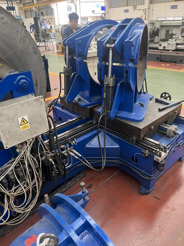
We inspect, maintain and upgrade hydraulic systems on industrial machinery, covering hydraulic cylinders, power units, pumps, valves, piping and control components. We also prepare Preventive Maintenance (PM) plans to catch faults before they cause damage and to schedule downtime at the right time.

Service Options
On-site assessment, component-only repair, removal and reinstallation, condition-based overhaul, and one-off or annual-contract PM. The inspection list, spare parts, downtime window and test conditions are agreed with the customer before work begins.
Hydraulic Cylinder Repair Scope
We trace the cause of oil leaks, loss of force, cylinder drift, jerky movement or abnormal stroke by checking the cylinder body, mounting points, load alignment and control circuit, so that internal seal leakage can be told apart from valve or oil supply problems.
Inspection and Repair Work
• Disassemble and clean, record part positions, and check for metal debris, contamination and the condition of the old seals
• Measure the piston rod, cylinder bore, piston, seal grooves and bushings; check straightness, scoring, rust, plating and wear against specifications
• Replace Rod Seal, Piston Seal, Wiper, O-ring, Backup Ring and Wear Ring according to the model and inspection results, selecting materials compatible with the oil, temperature and pressure
• Assess rod surface repair, re-plating, grinding, cylinder honing or manufacture of replacement parts to the agreed drawings and tolerances; this work is quoted separately based on condition
• Check threads, end caps, Tie Rods, mounting points, Pins and Bushes; reassemble to the specified torque and protect the ports from contamination
• Test movement, external leakage and internal leakage using the test method and values confirmed before handover

Replacing seals alone may not fix the root cause if the rod or bore is damaged, the installation is misaligned, or the system is contaminated, so the repair method is chosen after a joint assessment.
Hydraulic Machinery Repair Scope
Power Unit and Oil System
We inspect the Hydraulic Power Unit (HPU), including the pump, motor, coupling, oil tank, filters, Breather and Oil Cooler, checking noise, vibration, heat and air ingress, and measure pressure, flow or Case Drain where the equipment and test method for that model allow.
Valves and Control Circuits
We inspect Directional Valves, Relief Valves, Check Valves, Flow Controls and load-holding valves according to the circuit, and check coils, connectors, control signals and response. Electrical causes are separated from hydraulic faults before any repair or replacement, and pressure is never raised to compensate for worn components without an assessment.
Pipes, Hoses and Fittings
We inspect hydraulic hoses, fittings, flanges, rigid pipes, clamps, chafing points and hose routing, and replace parts with the correct pressure rating, material, thread and compatibility. Pressure Gauges, Pressure Switches, Sensors and Accumulators are also checked when they are within scope.
Machine Systems and Upgrades
We check cylinder mountings, travel alignment, guides and the operating sequence of presses, clamping units, lifting units and other hydraulic machines, and assess upgrades to cooling, filtration, measuring points and alarms based on the problems found, confirming suitability for each machine model.

Work Process and Testing
Step | Details and records required |
1 Information gathering and survey | Identify the machine, symptoms, repair history, system ratings and site constraints |
2 Analysis and scope proposal | Determine preliminary causes and define the teardown list, spare parts, repair method and downtime |
3 Preparation and energy isolation | Prepare safety documents, support the load, isolate energy sources and release residual pressure |
4 Teardown and confirmation of items | Tag ports and parts, measure actual condition, and report any additional damage for customer approval before repair |
5 Repair and reassembly | Control cleanliness, check parts and ratings, reassemble per the manual and record replaced parts |
6 Testing and handover | Test according to the plan, record before-and-after values, report limitations and outstanding work, and sign off the handover |
Post-Repair Testing Principles
Leakage and movement are checked without load first, then tested with a load the customer confirms is safe under the test plan. Pressure, temperature, stroke, extend and retract times, and position holding are recorded where relevant to the machine's function.
Test pressure, hold time, number of cycles and acceptable leakage must follow the manual or agreed specifications. The same pressure multiplier is not applied to every type of cylinder, and testing never exceeds the rating of the lowest-rated component in the test setup.
Acceptance Criteria
• No external leakage under the specified test conditions, and internal leakage within the limits for that model
• Movement, stroke, speed and position holding meet the agreed criteria, with no abnormal noise or jerking
• In-scope control systems and protective devices pass testing, with any items that could not be checked recorded
Annual Hydraulic System PM Plan
The plan below is a framework for service contracts, not a mandatory schedule for every machine. Intervals should follow the manual, operating hours, environment and machine criticality; where the manual specifies both time and operating hours, whichever comes first applies.
Recommended frequency | Main inspection items | Performed by |
Daily or before each shift | Oil level, leaks, noise, temperature, pressure and warning lights; record the readings | Operator or customer maintenance team |
Monthly | Rod and seal condition, hoses and fittings, mounting points, Cooler and filter clogging indicators | Maintenance team or service team |
Quarterly | Pressure and temperature trends, cycle times, recurring leaks, sensor signals and spare parts planning | Contracted service team |
Every 6 months | Review oil condition, consider sampling for analysis, check couplings and cooling performance | Service team, and a laboratory where specified |
Annually | Shut down for an in-depth inspection per the checklist below, review the year's results and plan major repairs | Service team together with the customer |
Condition- or hour-based | Replace filters, oil, seals and hoses according to the manual, inspection results, service life or abnormal signs | Person responsible as assigned in the plan |
Example Annual Service Schedule
A survey and baseline are established before the service cycle begins, followed by 4 visits: months 3, 6 and 9 to monitor condition, and month 12 for a major inspection during the annual shutdown. The actual number of visits and the initial survey are specified in the quotation, while operators continue daily checks throughout the year.
When to Increase Frequency
Machines running multiple shifts, in dusty or hot environments, exposed to water or metal debris, operating near their rated limits, or with a high impact on safety and production should have inspection intervals increased according to risk. Do not wait for the annual service when abnormal symptoms appear.
Annual PM Inspection Checklist
The actual list is adjusted to the model and installed equipment. Each result is recorded as Pass, Monitor, Correct or Not Applicable, together with measured values, photos and the inspector's name. Items not yet tested are never marked as passed.
System inspected | Inspection work and evidence |
Hydraulic cylinders | Rod and seal condition, leaks, mounting points, load alignment and play; test stroke and position holding as appropriate |
Pumps and motors | Noise, vibration, motor current, coupling condition, mounting base, and performance values that can be checked by the manufacturer's method |
Tank and oil | Level, colour, foaming, water, sediment and cleanliness; take samples for viscosity, water and particle testing when in scope |
Filters and Breather | Check clogging indicators, model and replacement history; replace per the manufacturer's criteria or inspection results. Disposable filters must never be cleaned and reused |
Cooling system | Check fins, fans, coolant flow where fitted, and temperature trends during operation |
Valves and Manifold | Check leaks, response, coils, wiring and Setpoint values against the approved circuit |
Hoses, pipes and fittings | Check for cracks, swelling, abrasion, rust, leaks, hose age, bend radius, clamps and routing at risk of chafing |
Accumulator (if fitted) | Check mounting, leaks and ratings; assess pre-charge pressure per the manual, by qualified personnel with dedicated equipment |
Instruments and sensors | Compare readings against reference instruments; external calibration is specified separately from general inspection |
Control and protection systems | Test Interlocks, alarms and Emergency Stop according to the machine's plan, in coordination with the person responsible for safety systems |
Running the machine after PM | Test without load and with the agreed load, re-check for leaks, and record pressure, temperature and operating times |
Condition summary and next year's plan | Prioritise urgency, estimate spare parts and Downtime, and set follow-up dates for defects |
Tank cleaning, oil changes, Offline oil filtration and Flushing are selected based on inspection results and oil compatibility. Overhauling pumps or cylinders every year is not always necessary and must be confirmed as a separate work item.
Safety, Quality and Handover Documents
Safety Controls Before Repair
We assess risks and prepare a JSA or Work Permit according to plant requirements, carry out Lockout Tagout (LOTO) on the relevant energy sources, and release and verify residual pressure in every section, including circuits with Check Valves and Accumulators. Mechanical supports are used for loads or parts that could fall or move.
The pressure test area is barricaded, and equipment ratings and tool readiness are checked. Hands are never used to search for high-pressure leaks, and fittings are never loosened while under pressure. Accumulator work uses the gas and charging kit specified by the manufacturer and is done by qualified personnel; oxygen or compressed air must never be used in place of nitrogen.
Cleanliness and Spare Parts Control
Ports are capped immediately after removal, assembly is done in a clean area, and parts are stored as sets. Part numbers and compatibility are checked, oils are never mixed without verification, and spills, oil and contaminated materials are handled according to the plant's procedures.
Documents That Can Be Included in the Service Scope
• Pre-repair and post-repair condition reports with photos and a list of damage
• List of replaced parts, with part number, size, quantity and material where known
• Test records stating ratings, conditions, measured values, instruments and results against the acceptance criteria
• PM Checklist, machine history, and a list of defects with follow-up dates
• Handover document and operating recommendations, including items outside the scope or not yet inspected
Service Terms and Warranty
Service fees, spare parts, transport, repair lead time, number of PM visits and warranty period are specified in the quotation based on the survey. Any additional damage found after teardown must be approved before work proceeds. The warranty covers work and parts under the agreed terms, with the cause assessed where contaminated oil, operation beyond rated limits or other parts of the machine are involved.